MULTI-SHEET FLAT DESIGNS
Introduction
With very large designs, or just to create some structure in smaller ones, it is common practice to draw the various sections of the design on separate sheets. Connections between the sheets are then indicated by means of common net names. For example, if two nets on different sheets are both labelled as MREQ, then they are assumed to be connected: see net names for more information on net names.
A flat design is one in which all the sheets sit at the same level, with no parent and child relationships between them. Where you want one sheet to sit inside another, see Hierarchical Designs.
Design Menu Commands
Proteus supports multi-sheet designs and keeps all the sheets of a design in one project file. The commands for creating and removing sheets are on the Design menu:
- New Sheet, creates a new root sheet and loads it.
- Remove/Delete Sheet, removes and deletes the current sheet. Only root sheets can be removed, and the command will not remove the last root sheet of the last board.
The Design menu also carries the commands that move you between sheets, described in the next section, together with Edit Design Properties, Edit Sheet Properties, Edit Design Notes and Configure Power Rails.
Navigation Commands
The following commands move you between the sheets of the design. They apply equally to a flat design and to a hierarchical one.
- Goto Previous Sheet, on the Design menu, moves you to the previous sheet in the design. It traverses the whole design, moving between root sheets and sub-sheets alike. The shortcut is PGUP.
- Goto Next Sheet, on the Design menu, moves you to the next sheet in the design, again traversing both root sheets and sub-sheets. The shortcut is PGDOWN.
- Exit to Parent Sheet, on the Design menu, leaves the current sheet and returns you to the sheet holding the module it belongs to. The shortcut is CTRL+X.
- Goto Sheet, on the Design menu, presents every sheet in the design as a tree, grouped under its board and indented to show the hierarchy, so that you can jump directly to any one of them.
- Goto Child Sheet, on the context menu of a module, enters the sheet attached to the module you are pointing at. The shortcut is CTRL+C.
- Goto Part in Design Explorer, on the context menu of a component, opens the Design Explorer with that part selected. The shortcut is ALT+X.
The shortcuts for Goto Previous Sheet and Goto Next Sheet are fixed and cannot be reassigned in the Edit Keyboard Map command.
The Design Explorer can also be used to navigate to a particular sheet, or indeed to a particular net or component, and provides a windows explorer style user interface for schematic navigation. Alternatively, the first ten root sheets of the design are listed and dynamically updated at the bottom of the Design menu whenever a root sheet is the current sheet.
The titles presented by the Goto Sheet command are taken from the Sheet Title field of the Edit Sheet Properties dialogue form. Where no sheet title has been given, a name is generated for you: root sheets are named Root sheet 1, Root sheet 2 and so on, the master sheet is named Master Sheet, and a child sheet is named after its parent module and its ordinal, in the form AMP:10. A child sheet whose parent module has not been named appears as <Un-named Child Sheet>:10.
Editing Sheet Properties
The Edit Sheet Properties command on the Design menu edits the properties of the sheet you are currently working on.
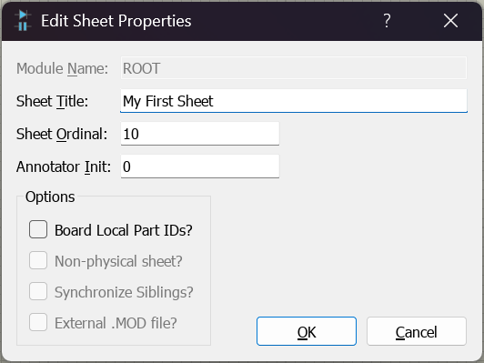
The Edit Sheet Properties dialogue form
The sheet ordinal determines the position of the sheet in the design, which is to say the order in which the sheets print if you print the lot, and the order in which they appear on the Design menu.
The annotator init property is an extremely useful property which lets you set an annotation base for all components on the sheet. It can both be set here and also, under certain circumstances, in the Global Annotator. When working with a large design hierarchy, a little discipline with sheet annotation can add clarity to the design.
The module name is the name of the hierarchy level the sheet belongs to. It cannot be edited on a root sheet, and the same is true of the Non-physical sheet, Synchronize Siblings and External .MOD file options below, all three of which apply only to sheets that sit inside a module.
Board Local Part IDs?
This option matters only in a multi-board project, and although you reach it from a sheet it is a property of the whole board rather than of the sheet you happen to be on.
When it is set, component annotation is local to the board. The automatic annotator considers only the references already used on that board when it allocates the next free reference, so U1 can exist independently on two different boards of the same project without clashing. When it is clear, references are allocated across the design as a whole and every reference in the project is unique. Boards created with the New Board command have the option set.
Board local annotation is generally the more useful choice, because it makes documentation such as the bill of materials and the assembly drawings easier to follow. The Automatic Annotator in the layout module also requires it: on a multi-board project it will offer to turn the option on for you rather than run without it.
Synchronize Siblings?
Where the same circuit name is given to more than one sub-circuit, each sub-circuit is an instance of one and the same circuit. The drawing itself is always shared: whatever you place, wire or move on one instance appears on all of them, and this is true whatever this option is set to.
What the option controls is the component data. When it is set, which is the default, editing a component on one instance also updates the matching component on every other instance of that circuit. The value, the property block, the PCB package and the assembly variant fitted state are all carried across. Component references are never carried across, so each instance keeps its own annotation.
Clear the option if you want the instances to be able to differ. Each instance then keeps its own component values and properties, while continuing to share one drawing. Like the circuit name itself, the setting belongs to the circuit, so changing it on one instance changes it for them all.
See Also: